KUKA KRC2: DSE-RDW Inconsistent — Serial / PID Stuck at 0 on the RDC
KRC2 DSE-RDW inconsistent with the serial number stuck at 0 on the RDC: what the RDC EEPROM stores, how to test the X21/X31 link, and when the board is really dead.
DSE-RDW inconsistent — serial / PID won’t write to the RDC (stuck at 0)
The serial is correct on the HDD side but reads 0 on the RDC; the HDD→RDC write fails and the inconsistency won’t clear — jumper, dead EEPROM, or something to force-init?
The question
The actual ask is three sharp questions: (1) is there a write-protect jumper on the RDC board that blocks the write? (2) does a stuck-at-0 serial confirm the RDC EEPROM has failed in hardware? (3) is there a low-level format / Monitor variable to force-initialize the RDC so the serial/PID can be re-written?
Short answer
$REBOOTDSE=TRUE only re-runs the DSE driver — it cannot repair a dead EEPROM cell.
What the manuals say the RDC stores (verified)
Two facts settle the ground truth: the RDC carries a robot serial number / robot number in non-volatile memory, and the controller actively cross-checks and (re)writes it. Both manuals corroborate:
| Point | KRC2 ed05 Operating Instructions | KSS System Messages |
|---|---|---|
| Serial / PID is in RDC EEPROM, persistent | §11.12.1, p.120: “The contents of the EEPROM in the RDC unit can be overwritten. These data cannot be restored simply by booting the system.” | — (consistent: the robot number is held “(RDC)”, see below) |
| A robot serial number is held in the RDC and checked | RDC table holds the hardware-configuration data of the RDC (§11.12.5, p.123) | Msg 271, p.48: “Robot no. <robot serial number (RDC)> does not correspond to calibration file” — the serial is explicitly tagged (RDC) |
| The number can be absent / unprogrammed | — | Msg 272 “No robot number programmed”; Msg 274 “Check robot number”; Msg 275 “Set robot number – program robot name” (p.48–49) |
| Write direction | EEPROM content is overwritten from the controller side (HDD/driver), §11.12.1, p.120 | The HDD→RDC direction is exactly your error string (“PID file write failure from hard drive to RDC”) |
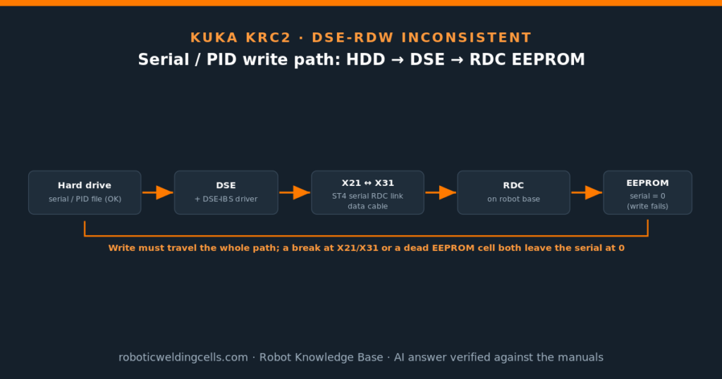
$REBOOTDSE) doesn’t fix a 0 — if the write didn’t land in the cell, there is nothing for the boot to read back.Where it sits: the HDD → DSE → RDC serial / PID path
The write the controller is attempting (HDD → DSE → X21/X31 → RDC EEPROM)
Path & interfaces: KRC2 ed05 Operating Instructions — ST3 drive bus / ST4 serial RDC interface = X21 (§2.3.1, p.14); connection panel X21 “RDC connection” and X31 “RDC connection on the robot base” (Fig. 2-28, p.39–40); data cable X21 axes 1–8 (§2.9.5, p.45). The EEPROM is read/written across this same serial link, so a flaky link can also break a write.
Question 1 — is there a write-protect jumper on the RDC?
The corpus describes the RDC EEPROM as overwritable from the controller with no jumper precondition (§11.12.1, p.120). If a board-revision jumper exists it is not a documented user setting; assuming one and moving it is exactly the kind of blind step to avoid.
Question 2 — does a stuck-at-0 serial confirm a dead RDC EEPROM?
It is consistent with it, but not proof. A read-back of 0 after a write attempt has more than one cause, and you must clear the cheaper ones first:
| Cause of “serial stays 0 / write fails” | How to tell it apart |
|---|---|
| Broken / intermittent RDC data link (X21–X31) | DSE-RDW shows transmission/communication errors; resolver positions read 0 or the comm-error counter climbs (§11.12.7, p.125–126). Related faults: 105 “Transmission error DSE–RDW”, 100 “RDW boot up failure”. |
| Wrong / missing RDC program (driver side) | 265 “RDW file not available” — the RDC program in RD_HWINF.INI is wrong/missing; the write tooling can’t address the RDC correctly. Check the INI entry. |
| RDC EEPROM cell actually failed | Link is clean (no 105/comm errors), the program is correct, the normal “set robot number” write is issued — and the value still reads 0. With the path cleared, a persistent write failure points at the EEPROM. A swap test confirms it. |
Question 3 — is there a low-level format / Monitor variable to force-init the RDC?
What is documented is the normal write operation: the system message set 274 “Check robot number” / 275 “Set robot number – program robot name” (System Messages p.48–49) is the supported way to (re)program the robot number/serial into the RDC. Note the manual itself defers the step-by-step for 272/275 (“Information can be found in the operating handbooks”) — so the corpus confirms that you set it, not the exact keystrokes; treat the detailed procedure as a gap to confirm on the machine / in the KSS operating handbook.
$REBOOTDSE=TRUE: this re-initializes the DSE driver / re-establishes DSE↔RDC communication. It is the right move to retry the link, but it cannot rewrite or repair a failed EEPROM cell — consistent with §11.12.1 p.120 (“cannot be restored simply by booting”). That it didn’t help is expected if the cell or the link is the problem, and does not by itself condemn the board.How to test — before condemning the RDC
- Open DSE-RDW and read the state.
Setup > Service > DSE-RDW(§11.12, p.120). Under 1.RDC2 > Check communication (§11.12.7, p.125–126) reset the counter (“Reset comm. errors”) and watch the communication-error counter / state (0001after >3 failed transmissions) and whether resolver positions are sane. Under 1.RDC2 > Table (§11.12.5, p.123) read the RDC config data (serial lives in this EEPROM block) and use Export to capture it. Clean comms + a 0 serial isolates the fault to the EEPROM/PID write, not the link. - Verify the X21–X31 data path end-to-end (power down first). Unmate the RDC data cable at both ends —
X21at the cabinet (ST4 serial RDC interface, p.14) andX31at the robot base (Fig. 2-28, p.39–40). Reseat both; inspect for bent pins / corrosion. With a multimeter, check continuity pin-to-pin end-to-end, and check no conductor is shorted to its neighbour or to the shield. Confirm the shield is continuous and bonded at both shells (a broken shield is the classic intermittent/transmission fault — cf. code 105). - Wiggle test (catches the intermittent break). Keep the meter on a suspect conductor and flex the cable along its length, especially at the
X21/X31strain-reliefs and any drag-chain points, watching for the reading to flicker open. A drop-out that appears only when moving the cable explains an inconsistent write that a static check passes. - Confirm the RDC program / INI. Make sure the RDC program named in
RD_HWINF.INIis correct and present (a wrong entry raises 265). A mis-addressed RDC can fail the write without the EEPROM being bad. - Re-attempt the documented write. As Expert/Administrator, issue the normal “Set robot number / program robot name” operation (msg 275) with the link confirmed good, then re-read the serial in the RDC table. Still 0 → the write is genuinely not sticking.
- Swap-test the RDC (the decision step). If a known-good RDC is available, substitute it and repeat the write. If the serial now programs and the inconsistency clears → the original RDC EEPROM is the fault (confirmed by substitution). If a good RDC also won’t take the write → the problem is upstream (DSE / driver / INI / cable), not the EEPROM.
Could it be something other than the EEPROM?
Worth ruling out, because each surfaces differently and points away from a board swap:
| Alternative | Signature | Verdict |
|---|---|---|
| DSE–RDC link fault (cable/connector) | 105 “Transmission error DSE–RDW” / 100 boot-up failure; DSE-RDW comm-error counter climbs | Check first — cheapest fix; your write rides this link |
| Wrong RDC program / INI | 265 “RDW file not available”; write tool can’t address RDC | Quick to verify in RD_HWINF.INI |
| DSE / DSE-IBS side fault | 101 “DSE boot up failure”; DSE state abnormal in DSE-RDW | Less likely if other axes/feedback work; the swap test separates DSE from RDC |
| RDC EEPROM cell failed | Link clean, program correct, write still reads back 0 | Most likely once the above are excluded — confirm by swap |
Open points / to verify
- Write-protect jumper: none documented in the corpus — if a hardware revision has one, it is not a documented user setting (gap).
- Low-level format / force-init: no documented EEPROM “format” or Monitor variable; only the normal “set robot number” write exists (gap — do not improvise a format).
- Exact “set robot number” keystrokes: System Messages 272/275 confirm the operation but defer the step-by-step to the operating handbook (“Information can be found in the operating handbooks”) — confirm on the machine / in the KSS handbook.
- RDC connector pin map: the X21 data-cable pin allocation in §2.9.5 (p.45) is a figure; read the exact pinout against the cabinet wiring diagram before pin-to-pin metering.
- Model: the Operating Instructions in the corpus are KRC2 ed05 (V3.3, 2007); on an older KRC2 the DSE-RDW menu path may differ slightly — confirm on the controller.
Sources: KRC2 ed05 Operating Instructions — ST4 serial RDC interface / X21 (§2.3.1, p.14), connection panel X21 & X31 RDC connection (Fig. 2-28, p.39–40), data cable X21 (§2.9.5, p.45), DSE-RDW diagnosis incl. EEPROM-overwrite note (§11.12.1, p.120), RDC table (§11.12.5, p.123), check RDC–DSE communication (§11.12.7, p.125–126). KSS System Messages — 100 RDW boot-up failure (p. 17), 105 transmission error DSE–RDW (p. 19), 265 RDW file not available (p. 46), 271 robot no. (RDC) vs calibration file (p. 48), 272/274/275 robot-number programming (p.48–49). Fault Listing Manual — 100, 102, 105, 265 (corroborating).
Have a question about your robot?
Any brand, any controller, any age. Describe the problem, add a photo, and get a clear technical answer for free.
AI-generated answer verified against the official manufacturer manuals. For informational purposes only — it does not replace the manufacturer’s official documentation or safety procedures.
Related articles
Request a quote
Looking for a specific configuration, or want to discuss our current stock? Tell us about your project — we reply within 24 hours from our Bilbao office.