KUKA KRC2: Recalibrating a Rotary Table — Mathematical Coupling Step by Step
How to recalibrate a rotary table on a KUKA KRC2 so the robot tracks it again: TCP, root point, offset base BASE_DATA[17..22] — and why not to edit $MACHINE.DAT by hand.

Recalibrating a rotary table so the robot tracks it again (mathematical coupling)
The robot and table lost sync after the cell was moved and the tool changed — how to bring the coupling back, and what not to hand-edit on KSS 5.4.
The question
After the robot and the table were physically repositioned and a new tool was fitted, the robot no longer follows a point on the rotating table. The real question is which calibration data the move invalidated, in what order to redo it so mathematical coupling works again, and whether the fix is editing $MACHINE.DAT by hand or re‑running the start‑up calibration.
Short answer
BASE_DATA[17…22], then jog/program with that offset base selected — this is the “base 17” often referred to in the field, and the manual confirms it is exactly what switches mathematical coupling on. Another common field shortcut — hand‑editing $ETx_TPINFL in $MACHINE.DAT so it isn’t zero — is the pre‑5.3 method: on your KSS 5.4 that reference‑pin offset is entered as a tool, not as machine data. The kinematic geometry of the table itself did not change, so you should not need to re‑edit the $ETx_* transformation.
What “mathematical coupling” needs (verified)
An external kinematic system can move in two ways. The distinction is the whole problem here:
| Field | Synchronous, mathematically coupled | Synchronous, NOT coupled (static base) |
|---|---|---|
| What the robot does | “The robot calculates its motion path in relation to the position of the kinematic system” — it tracks the point on the table. | “The robot calculates its motion path without taking the position of the external axis into consideration.” |
| Calibration | “The kinematic system must be calibrated.” | “The external axis need not be calibrated.” |
| How it is activated | Teach/program the motion relative to the moving offset base (BASE_DATA[17…22]). |
Teach/program relative to a static base. |
Definitions: External Axes — Setup & Programming (KSS 5.5), §2.3, p.12. Coupling vs. static base in programming: §9.2, p.93–94.
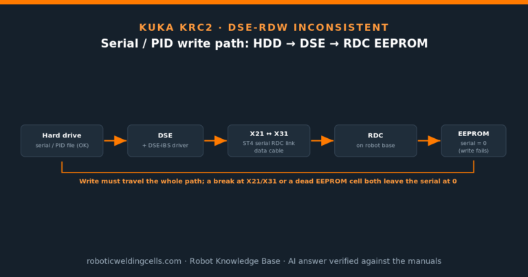
Where the data sits: the table’s transformation chain
What the move and the tool swap invalidated
Transformation variables and chain: External Axes — Setup & Programming (KSS 5.5), §7.3.1, p.61–63; worked DKP 400 example with $ET1_TPINFL, Fig. 10‑2, p.102. The green items are what the cell move / tool swap invalidate; the orange items describe the table’s own geometry, which did not change.
Step 0 — preconditions before you calibrate
Calibration is a start‑up task: T1, no program selected, Expert user group. If the external axis itself was disturbed mechanically, master it first via Setup > Master > Dial gauge; otherwise leave mastering alone. The manual is explicit that calibration is what makes coupling possible at all: “Calibration of a kinematic system is necessary to enable the motion of the axes… to be synchronized and mathematically coupled with the robot axes.”
Mastering with the dial gauge: §6.1.5, p.45–48. Calibration purpose: §6.2.1, p.49.
Steps 1–4 require jogging the robot and the external table in
T1 and driving the TCP onto a physical reference point. The robot is energized and moving: keep clear of the pinch zone between tool, pin and fixture, jog at reduced override, and stay outside the table’s swing radius. Qualified personnel only.
Step 1 — re-measure the new tool (TCP) first
Every calibration step below moves a previously calibrated tool to reference points — the root‑point method’s precondition is literally “A previously calibrated tool is mounted on the mounting flange.” Because you changed the tool, its TCP must be re‑measured before anything else, or every later step inherits the error. Re‑measure with the standard tool calibration (XYZ 4‑point + ABC), or enter it numerically via Setup > Measure > Tool > Numeric Input if the values are known.
Step 2 — re-calibrate the table’s root point
The root point is the controller’s knowledge of where the table is: “In order to be able to move the robot with a mathematical coupling to a kinematic system, the robot must know the precise location of the kinematic system. This location is determined by means of root point calibration.” Moving the robot and table relative to each other is exactly what invalidates it. Two sub‑steps:
- Assign a reference point as a TOOL. A fixed measuring point (the reference pin) on the table is entered as a TOOL coordinate system, relative to the table’s flange:
Setup > Measure > Tool > Numeric Input. The manual requires that “Reference point and flange center point must be sufficiently far apart” — this is the documented form of the field rule “this value cannot be zero.” - Touch the reference point in 4 different table positions.
Setup > Measure > External kinematic > Root point; jog the table to a new angle and drive the TCP onto the reference point, Measure, repeat 4×, Save. The controller computes the root point from the four positions. If the location is known from CAD, enter it numerically via… > Root point (numeric)instead.
Root point purpose & steps: §6.2.2–6.2.5, p.50–52. “Sufficiently far apart”: §6.2.3, p.51.
Step 3 — re-calibrate the offset base (this is “base 17”)
The moving base that rides with the table is the offset base: “a moving base that moves in the same way as the kinematic system… its reference point refers to the flange center point of the kinematic system and not the WORLD coordinate system.” Its coordinates live in BASE_DATA[17…22], and only one offset base exists per kinematic system. Teach it by touching three points with the calibrated TCP:
Setup > Measure > External kinematic > Offset; name the kinematic system, enter the mounted tool number.- Drive the TCP to the offset‑base origin (Continue), then a point on the +X axis (Continue), then a point in the XY plane with +Y (Continue), then Save. Those three points define the base.
Offset base definition, BASE_DATA[17…22], 3‑point procedure: §6.2.6, p.52–53.
Step 4 — activate the coupling and test
Coupling is not a separate “mode” switch — it is which base the motion is relative to. The manual states it directly: “To activate mathematical coupling, select the offset base in the option window Frames as the base to which the robot motion is relative. The coordinates of an offset base are saved as BASE_DATA[17…22].” So program the motion with that base selected:
; coupled — robot tracks the rotating table
PTP P10 VEL=100% PDAT50 Tool[1]:Pen Base[17]:TABLE
LIN P11 VEL=0.2m/s CPDAT1 Tool[1]:Pen Base[17]:TABLE
Test by jogging E1 (the table) a few degrees with the TCP held near the reference point: with the offset base selected, the TCP must stay on the point as the table turns. If it does, coupling is restored.
Base[17]:TABLE → Base[0]. You do not need a decouple function for that.Should you edit $ETx_TPINFL in $MACHINE.DAT?
This is where the common field shortcut is half‑right and worth pinning down. $ETx_TPINFL is the offset from the table’s flange center point to the reference pin (in the manual’s DKP 400 example, $ET1_TPINFL={X 210.0,…}). The pin offset is real and must be non‑trivial — but on your KSS it is no longer a machine‑data value:
| Aspect | What the manual says | Implication for KSS 5.4.14 |
|---|---|---|
Role of $ETx_TPINFL |
“Translation… from the flange center point to the reference pin.” | Describes the measuring‑pin offset — conceptually the “distance that can’t be zero.” |
| Still used in the transform? | “The transformation from the flange to the reference pin $ETx_TPINFL is no longer taken into consideration. Since software version 5.3, these data must be entered numerically as a tool.” |
5.4.14 is post‑5.3 → do not hand‑edit it; enter the pin as a TOOL in Step 2. |
| DKP 400 example note | “These data are no longer relevant for the transformation. They must be entered numerically as a tool.” | Same conclusion, stated again at the worked example. |
Sources: §7.3.2, p.64; worked example lines & note, p.103–104.
$ET1_TA1KR, $ET1_TFLA3…) did not change when you moved the cell, so leave $MACHINE.DAT alone. Editing $ETx_TPINFL by hand is the older (pre‑5.3) workflow and will not be honoured the way that shortcut assumes.Open points / to verify
- Version drift on menu labels. The corpus is KSS 5.5; you run KSS 5.4.14. The variables and method are the same, but exact softkey/menu wording on your pendant may differ slightly — confirm
Setup > Measure > External kinematicon the controller. - We can’t see your machine data. This answer assumes the table’s mechanical geometry was unchanged by the move. If the table itself was rebuilt or the axis re‑geared, the
$ETx_*transformation would also need revisiting — not the case for a simple reposition. - Mastering. If the external axis lost mastering (encoder/brake work, mechanical knock), redo it (§6.1.5, p.45–48) before Step 2; otherwise skip it.
- Single‑axis vs. multi‑axis table. Steps are written for a one‑axis rotary (E1). A 2‑axis tilt‑rotate positioner adds
$ET1_TA2A1to the chain but the calibration sequence is identical.
BASE_DATA[17…22] activates mathematical coupling), the calibration sequence (TCP → root point → offset base), and the $ETx_TPINFL‑as‑tool change since KSS 5.3. Medium on the case specifics (machine data not inspected; assumes table geometry unchanged and tool swap as the only fixture change).Sources: External Axes — Setup & Programming (KSS 5.5) — coupled vs. non‑coupled p.12; programming coupling p.93–95; mastering (dial gauge) p.45–48; calibration purpose p.49; root point p.50–52; offset base
BASE_DATA[17…22] p.52–53; transformation variables p.61–64; $ETx_TPINFL worked example p.102–104.
Have a question about your robot?
Any brand, any controller, any age. Describe the problem, add a photo, and get a clear technical answer for free.
AI-generated answer verified against the official manufacturer manuals. For informational purposes only — it does not replace the manufacturer’s official documentation or safety procedures.
Related articles
Request a quote
Looking for a specific configuration, or want to discuss our current stock? Tell us about your project — we reply within 24 hours from our Bilbao office.