Robotic Welding Cells, ready to weld in weeks — not months.
Fully inspected and refurbished welding cells from Fanuc, ABB, Yaskawa, KUKA and Panasonic. Save up to 60% vs new. Immediate availability. Delivered and commissioned anywhere in the world.
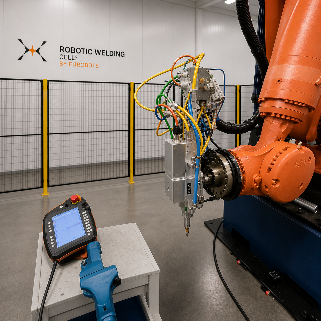
KUKA KR210 + Raycus 3kW Fiber Laser
- +3 kW fiber laser, cutting and welding
- +KUKA KR210 R2700, 6-axis, 210 kg payload
- +Ready to ship from Bilbao warehouse
Second-hand doesn’t mean second-rate.
Every welding cell we sell goes through the same five-step process our engineers have refined over 25 years of reselling industrial robotics.
Full technical inspection
Mechanical checks, axis calibration, brake tests, wiring inspection, power source diagnostics. Full written report provided.
Refurbishment as needed
Worn parts replaced with OEM components. Cables, torch, wire feeder, safety devices serviced or renewed.
Tested under load
Every cell is powered up, programmed and run with real welding cycles before it leaves our warehouse.
6-month warranty
Standard warranty covers core components. Extended cover and on-site support available on request.
Worldwide shipping
We handle crating, shipping, customs, and on-site commissioning. 40+ countries served to date.
40–60% less than new
Same performance, fraction of the cost, and delivered in weeks rather than the 6-9 months lead time of a new system.
Find the cell that fits your workshop.
Filter by cell type, robot brand or welding process. Browse current stock — 14 cells and configurations online, 20+ available at our Bilbao warehouse. Request your match today.
By Cell Type
By Robot Brand
By Welding Process
Answers buyers usually ask.
Are used welding cells reliable?
Yes. Every cell we sell is fully inspected, tested under load with real welding cycles, and refurbished by our robotics engineers. We provide a written inspection report and a 6-month warranty on core components.
How much can I save buying a used welding cell vs new?
Typically between 40% and 60% compared to the list price of an equivalent new cell. Delivery is also much faster: 2-6 weeks vs the 6-9 months lead time of a new integrated system.
What welding processes do you stock?
We specialise in MIG/MAG and Laser welding cells. Other processes (TIG, Sub-arc, Plasma) are covered in our Knowledge Hub but are not part of our standing inventory.
Do you ship worldwide?
Yes. We ship from our warehouses in Spain and Italy to the entire EU, UK, North America, LATAM and MENA. We handle crating, shipping, customs and on-site commissioning.
Ready to talk to a welding cell expert?
Tell us what you need to weld — we’ll reply within 2 business hours.
Not sure where to start?
Get a free ROI analysis for your part
Send a photo of your part and a few production numbers. We will send a personalized ROI report to your inbox within 48 working hours.
Start your free analysis →Free. No commitment. No sales pressure.
Talk to a welding cell expert
Pick a quick call. We will review your specs and find the best match from our 20+ cells in stock.